Networking Primer – Part 8: Summary

Holy cow, when starting to write this series I in no way expected it to turn into a 12 part, 3 month process.  I have covered so much, but there is so much more that could have been covered.  It’s been a challenge to keep pulling back and remembering that this is just a primer. To recap what we’ve covered by post:

Part Description
Part 1: Introduction Introduction to series content and objectives.
Part 2: Defining Networking with OSI and TCP/IP Suite Defining networking background, terminology and models.
Part 3: Application, Presentation and Session Layers Describes the tope 3 layers of the OSI model.
Part 4: Transport Layer, TCP and UDP A dip into the world of connection-orientated vs connectionless protocols.
Part 5.1: Network Layer – IP Addressing IP Addresses, what they are and how they are used.
Part 5.2: Network Layer – DNS and DHCP Converting IP addresses to names we can read and handing them out on a network.
Part 5.3: Network Layer – IP Routing Getting IP packets from one node to another.
Part 6.1: Data Link Layer, Ethernet and MAC Ethernet Frames for shifting local traffic.
Part 6.2: Media Access Control – CSMA/CD, CSMA/CA Getting access to the wire, fibre or air.
Part 6.3: Layer 2 Switching – Loops, Spanning Tree and Topologies Fitting LAN switches together,
Part 6.4: VLANs and other ANs (Area Networks) Security and Isolation with VLANs
Part 7: Physical Layer, Electrons, Photons and All Things Quantum Physical media and nerdiness.
Part 8: Summary Summary.

I’ve really enjoyed refreshing all my own knowledge on these basic concepts and hope you have too. Future series are to be more specifically focussed on network virtualisation and other areas of the data centre.

Networking Primer – Part 7: Physical Layer, Electrons, Photons and All Things Quantum

Our 7th and Final OSI Layer is the Physical Layer. Unless you are planning to work with or design specialist hardware there isn’t much interaction required with this layer from an administrative point of view. We’ll cover some of the basics here but not in-depth.  This layer strays directly into the realms of science, more specifically physics and even more specially quantum physics.  This is most definitely the geekiest post in this series.

Most modern computers store, process and transmit data in its simplest form, binary. It makes sense to encode data in the form of binary as even the most complex information can be broken down and represented as combinations of simple 0s and 1s. This simple representation maps very conveniently across to physical properties.  The physical technologies we use today work on the premise of data being represented by one of two states, there or not there (on or off).  The electronic components inside a computer are able to create and detect physical state. To simplify this to the highest level, electrical current is either present or not present inside a component on a circuit board. If it is present, that represents a 1 and if it is not, the represents a 0.

Signalling and Media

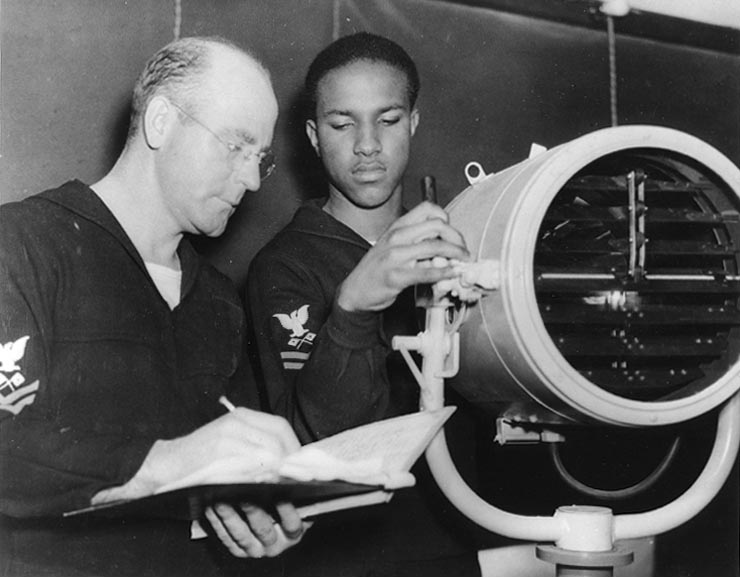
This is much easier to visualise in networking terms. If you have two nodes connected with a copper wire, the sending node is able to transmit electrical pulses down the wire and the receiving node is able to decode this as a stream of 0’s and 1’s. Another way of thinking of this is like the ships of World War 2 that used big lights to send messages to each other in the form of morse code. This is referred to as signalling and the whole focus of layer 1 is to define the protocols for converting data to signals along with sending/receiving them.  Anything that is able to exist (and be detected) in one of two physical states can be used as a transmission device.

Morse Code Signalling Lamp

Our transmission media doesn’t necessarily have to be electrons flowing down an electrically conducting wire. It could just as well be photons of light travelling down a fibre optic cable. It could also photons travelling through the air as part of radio magnetic waves (i.e. Wifi). When implementing the physical network, consideration must be given to the properties of the physical media, each of them will have different speed, throughput, cost and flexibility attributes. For instance, Fibre optic technologies generally cost more than their electron shuffling equivalents, but today they represent the fastest possible method moving signals from one place to another. They do this at the speed of light (299,792,458 metres per second) and that is essentially the fastest anything can travel as it’s the cosmological speed limit of the entire universe. Electrical current still moves down wires pretty fast, in fact almost at the speed of light, but slightly less due to other physical factors that cause some interference and resistance to the movement.

From a WiFi perspective it’s strange to think that we have electromagnetic waves running through us and all around us at all times. The transmission element in the radio wave is of course also the photon, after all, light is just an electromagnetic wave oscillating at a different (and visible) frequency than radio. I particularly like the picture below which visualised the electromagnetic wave of WiFi propagating across a city.

Here's What Wi-Fi Would Look Like If We Could See It

You can find more cool WiFi visualisation here:

Here’s What Wi-Fi Would Look Like If We Could See It

Wow, time to make our way out of the land of geek.  This is as much as we’ll cover here as this is a Primer and not a physics course.

Networking Primer – Part 6.4: VLANs and other ANs (Area Networks)

Previous: Part 6.3: Layer 2 Switching – Loops, Spanning Tree and Topologies

I probably should have covered this a little earlier in the series, regardless we’ll do it now. Networks are loosely categorised by the area they cover. This is usually compacted into a useful xAN acronym where x stands for the scope, A stands for Area and N stands for Network. The following table lists the different scopes:

Scope Description
LAN – Local Area Network Usually restricted to a single building or even sub-parts of the building in some cases. This type of network is most relevant to everything we have discussed at Layer 2 of the OSI stack. Primarily related to wired network connectivity.
WLAN – Wireless Local Area Network Very similar to LAN, but focussed on wireless connectivity as opposed to wired. Usually restricted to a single building or even sub-parts of the building in some cases. This type of network is most relevant to everything we have discussed at Layer 2 of the OSI stack.
WAN – Wide Area Network The largest scope of network that could potential span the entire globe.
MAN – Metropolitan Area Network Still large but restricted in size to Metropolitan area such as a city or large suburb.
CAN – Campus Area Network Multibuilding networks deployed across educational or similar institutional campuses.
PAN – Personal Area Network Used for devices in your immediate personal space or within a few meters. Smart phones and other Bluetooth driven devices sit in this category.

One acronym missing from the above table is VLAN – Virtual Local Area Network. Let’s put some focus on it now.

VLAN – Virtual Local Area Network
The reason I’ve missed it from the table is because a VLAN doesn’t really fit into a physical scope. It’s actually a logical segmentation construct that sits inside an existing Local Area Network or LAN.

Remember the importance of the Port as a management entity as stated in the previous post? This comes into play again here with VLANs too. By assigning a VLAN to a port we effectively segment it from the rest of the ports in the environment that aren’t assigned to the same VLAN. Without VLANs, every device connected to every switch in the network sits in the same Broadcast domain. Once the switches have learned which ports are occupied by which MAC addresses, broadcasts are reduced, but they do still need to happen as network changes are made frequently. By assigning VLANs, we are logically splitting down the broadcast domain into multiple smaller broadcast domains. Another more dynamic way to establish VLAN membership is by MAC address. This means that whichever port in the network a device is plugged into, it will always be recognised as a member of the correct VLAN.

So why would we want segment at all? There are two reasons, Security and Network Efficiency.  From a security perspective, by creating this logical segmentation we stop nodes from receiving frames that they do not need to receive, as all broadcast traffic is isolated to the ports that belong to the correct VLAN. This is can prevent an eavesdropping or any other unwanted visibility of frames outside of the VLAN. We might want to segment different departments in this way. For example, the payroll department might sit on its own VLAN, as the data it transmits is financially sensitive. Do all the nodes in the other departments need to see those broadcasts? Probably not. Network Efficiency is pretty straight forward too. By segmenting the traffic into VLAN we also reduce the amount of traffic each node receives. This reduces the amount of bandwidth used by the node and also the amount of processing the node has to do, to work out if the unwanted frames are intended for it, before discarding them.

While VLANs are an excellent tool for subdividing broadcast domains, we can take this even further if required using PVLANs (Private VLANs). A detailed description of the PVLANs is out of scope for this primer, but as a high level summary we can say that they are used to subdivide VLANs into even smaller broadcast domains. We create some secondary VLANs and then implement some rules to restrict which ports in the Primary VLAN each sub-division can communicate with. A good example use case for this might be a hotel network, where we want all devices to be able to communicate with the internet connected router, but not with each other. More details can be found here : Private VLANs.

Networking Primer – Part 6.3: Layer 2 Switching – Loops, Spanning Tree and Topologies

Previous: Networking Primer – Part 6.2: Media Access Control – CSMA/CD, CSMA/CA

We were briefly introduced to devices called Network Switches in the last post in this series. A switch essentially acts as a central connection point in a star topology  for many network nodes.It is similar to a Hub from a topological perspective but whereas a hub will take a frame in from one port and broadcast it out on all of the other ports, a switch has some built-in intelligence so it may forward the frame only to those ports which should receive the frame.  I like to think of a switch very much like it’s similar namesake, the switchboard, from the public telephony world.

Old Telephony Switchboard

In this older world, you picked up your phone to call the operator.  When the operator at the other end answered, you would tell her/him who you would like to call, they would cross reference the name with the relevant port number on the switchboard and plug in a cross-connecting wire between your incoming port to your outgoing call recipients. A network switch operates in a similar fashion although there are of course some notable differences.

Switch Ports

Ports are a very important entity in the switching process. Modern switches can contain 8, 16, 24 .. or even 1000’s of ports in large-scale enterprise level implementations. Port occupancy on a network switch can be very transient with desktops and laptops changing the port they are plugged into on a daily basis. To cope with this, the switch must be much more malleable and must have a mechanism for learning which device is occupying which port. It does this by maintaining a table of the source MAC addresses it receives from each port.  It is worth being aware that if a switch doesn’t know which port of the destination MAC address it will still broadcast to all the other ports in the same way a hub does.

I can’t emphasise the following enough, so it is worth re-iterating.. the Port is a very important entity in the switching process and is not only a node’s physical access point into the network.  It also represents a management construct that can be used to control the nodes security and resource permissions within the network.  The Port and it’s associated ID can be used to segment traffic as well as shape it (e,g, restrict bandwidth, etc).

Switching Topologies

A single switch device connecting all the nodes in a network is a pretty simple architecture to visualise and understand. This kind of set-up is however only found in small office environments. In larger environments, it may become impossible to cable all of the nodes into the same switch due to geographical, redundancy or resiliency factors.  In these environments, we need to introduce multiple interconnected switches.  Luckily most modern switches have the intelligence to connect to other switches in pretty much any configuration. We can daisy chain them together, make circular loops or any other artistic creation we wish.. all of these are possible:

Logical Topologies

When a switch is connected to another switch, it soon learns that the interconnecting port isn’t occupied by a single node and MAC address. They’ll learn that there is another switch there and that the port is possibly the destination for many devices. Any source MAC addresses coming in from that port will be stored in the table so that local nodes may send frames back to those devices via that port.  Given this flexibility, of connecting switches together in any configuration, it is possible to find ourselves with the problem of circular switching loops.

Switching Loops and the Spanning Tree Protocol

As stated above, if a switch receives a frame on a port and hasn’t yet learned the forwarding port of its MAC Address, it will broadcast it out on all of its ports with the exception of the one it receives it from. This is called a broadcast of an unknown unicast frame. A similar bulk multi-port forwarding operation may occur for general broadcast frames as well as multicast frames (frames for more than one destination node).  These multi-port broadcast have the potential to turn into infinite circular loops where there is a circular route to follow in an architecture.

Take the following example:

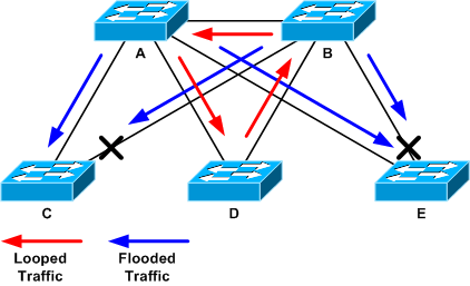
Switching Loops

A node connected to Switch B wants to communicate with a node connected to Switch C. It doesn’t know where the forwarding port for this node is so Switch B broadcasts to all ports including the ports interconnecting A, C, D & E. Switch A will send it to C, D & E. The frame will reach its destination on Switch C, but it may receive two copies of the frame, one from B one from A. Also now that D is in the mix, it’s possible D could broadcast it back to B, who in turn will broadcast it back to A. This is just one example of a switching loop.

The problem with these loops is that they’re often difficult to spot. The frame does get where it’s going, but multiple copies of it are being looped. This is only really apparent when the switches CPU seems to be increasing workload for no apparent reason. Enter STP or Spanning Tree Protocol. In Brief, STP learns the multiple possible routes a frame may take across the switching infrastructure. It then assesses these multiple routes using an algorithm to select the best one and blocks the rest, thus preventing any looping.

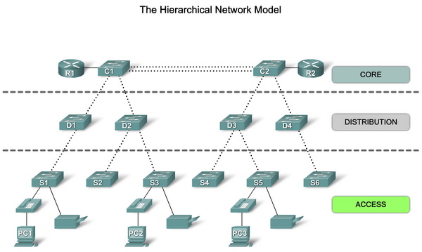
The Hierarchical Network Model

The Hierarchical Network Model is a network design model created by Cisco. It’s a very simple layered model created from medium or large network environments. The Layers are defined as follows:

  • Core Layer – composed of powerful high throughput switches and border routers to make up the backbone of the network
  • Distribution layer – a second tier layer used for aggregation the lower layer switches and connecting through to core.
  • Access Layer – the tier containing the front-end switches where the network devices/nodes gain access to the network.

The Hierarchy Network Model


This model is very widely deployed and has become somewhat of a defacto standard. It is worth remembering these layers and where they sit. In future blogs, I intend to address network virtualization and how it has shifted the dotted line and pulled some of the access layer into the hypervisor (more to come on this later).

 Next: Part 6.4: VLANs and other ANs (Area Networks)

Networking Primer – Part 6.2: Media Access Control – CSMA/CD, CSMA/CA

Previous: Networking Primer – Part 6.1: Data Link Layer, Ethernet and MAC

I will start this post with a foreword that at least one of the protocols in the title, CSMA/CD, is obsolete. I’m including it here as it’s very useful to understand why we no longer need it, due to the changes in layer 2 topologies that have evolved over time. A little history can illuminate why we are where we are.

CSMA (Carrier Sense Multiple Access) is a methodology that deals with multiple computing nodes access the same physical media, whether that be a piece of wire, optical fibre or even the air.  It makes sense that there should be some rules around when each node can transmit/receive rather than a free-for-all where interference, possible corruption and inefficiency can occur. The media is being shared so access needs to be given through arbitration.

There are two sub-methodologies for CSMA. These being CSMA/CD (Collision Detection) and CSMA/CA (Collision Avoidance).

CSMA/CD history

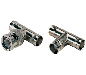
As mentioned in the previous post, initially Ethernet systems were based on coax (coaxial cable). Networks were implemented in a bus sharing topology. All of the nodes in the network would share the same piece of coax and essentially have their NIC connected to a piece of coax that was piped directly into the main bus coax via a T-Bar connector, that looked like this:

Coax T-Bar

You can see a typical network bus topology here:

LAN Bus Topology

In order to ensure communication between the nodes could occur. CSMA/CD was used. In CSMA/CD, each node would step through a process to get the desired result. The process was as simple as:

  1. Listen to see if the wire is idle.
  2. If idle, transmit the data.
  3. If a collision occurred with another node transmission, wait a random period of time then try again.

In this topology, we have to be aware that the wire represents what we call a “collision domain”. While using a single collision domain (i.e. wire) was reasonably efficient for a small number of computers, it had many problems with reliability and scale. From a reliability perspective, if there was a break anywhere in the wire, it would take down the whole domain. Another common problem was the absence of or faulty terminators (labelled Terminating resistor above).  Without a functioning terminator on the end of the coax, the bus wouldn’t function. A secondary issue here was scale. The more nodes you added, the more collisions you’d see and the less well the network would function.

There were several approached developed to mitigate these issues, revolving around the idea of breaking networks down into smaller segments and therefore smaller collision domains.

Network Hubs

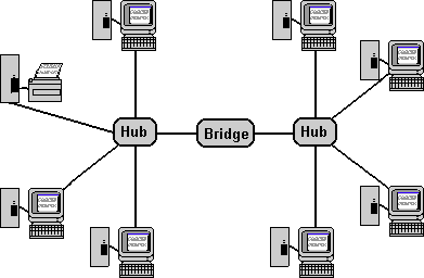
The coax bus topology was soon dumped in favour of using Twisted Pair (TP) cabling and a star/mesh based topology. In order to move away from the single wire bus topology, a new device needed to be introduced to act as the central connection point for the network, as each node would now have it’s own wire. Enter the hub. A hub is essentially a box with a bunch of ports on it. Each node can be plugged into a separate port on the using it’s own TP cable that has an RJ45 connector on each end. Using a star topology, with our nodes sitting on spokes around our hub, does resolve some of our reliability problems. If a wire breaks or is faulty, only the node sitting at the end of it is affected and not the whole network.

Hub Topology

The hub is, however, a very dumb piece of equipment. It takes frames in on any single port and then sends those frames out to every other port. From a collision perspective we still only have a single collision domain. This means that we still have to use CSMA/CD and we still have problems with scaling.

 Network Bridges

A network bridge is an additional network device that has a little more intelligence, but only a small step up from a hub. A bridge only has two ports, it sits between two network segments and learns which mac addresses sit on either side of it. If it sees a destination MAC address coming in from side A, and it knows that the destination node is on side A, it will drop the frame. Therefore, none of the nodes on side B will ever see it. We have reduced our network traffic by 50% on each side and also halved our collision domain.

Network Bridge


Network Switches

While Hubs and Bridges made significant strides in improving both reliability and reducing collision domains, it was clear that scale and management were still difficult for any network that was larger than a few 10’s of nodes. The network needed additional intelligence.  That intelligence came in the form of “Switching” and the new device to do that was the “Network Switch”.

The switch takes things much, much further. A switch has more than two ports, topologically it can be used instead of a hub. In the same way as they do to a hub, each of the nodes connects directly into the switch on a port. The switch is able to do the same sort of filtering that a bridge does, but it can do that on a per port basis. Rather than separating two network segments like a bridge, the switch is separating each and every node. When a frame comes in on one port, the switch is intelligent enough to send it out only on the port (or ports) where it needs to go to, to reach its destination. It has the intelligence to learn which MAC Addresses are sitting on which ports and updates its own internal tables as this changes.

Circling back to our title, bus using a switch we have effectively reduce our collision domain to a single wire per node. We therefore no longer need a methodology to arbitrate access to the media. Hence the obsolescence of CMSA/CD.

This is as deep as we’ll go on switching until the next post.

CMSA/CA – Carrier Sense Multiple Access – Collision Avoidance

CSMA/CD is very much the bull in a china shop, feet first approach to accessing physical media. CSMA/CA represents a more cautious approach with the goal of avoiding any collisions in the first place. It is still relevant and prevalent today due to the nature of WiFi networks.

In a WiFi network, the physical media is essentially the air (or radio waves running through it). As you can imagine, it would be very difficult to segment air in the same way as a wired network as there are no clear points in ingress/egress. We could try to use the CSMA/CD approach, but this isn’t effective in WiFi as each node communicates directly with the wireless AP (Access Point) and not with each other. This is called the hidden node problem, where collisions can’t be detected so the node never knows one has occurred. By using CSMA/CA, the WiFi network is able to work around the issue. With this methodology the AP mediates access to the media. A node requests permission to send, the AP gives the node a CTS (Clear To Send) acknowledgement and the node will send its entire payload across the channel. Only one node at a time has access to the channel.

Now we have successfully accessed or media and pushed our frame out of the source node, let’s look at how that’s moved across the LAN.

Next: Networking Primer – Part 6.3: Layer 2 Switching – Loops, Spanning Tree and Topologies

Networking Primer – Part 6.1: Data Link Layer, Ethernet and MAC

Previous:Networking Primer – Part 5.3: Network Layer – IP Routing

In previous posts we’ve covered logical addressing and moving IP packets of data across our network from source to destination. We’re now going to take a further shift towards the bits and bytes details of how that logical addressing and routing relates to the more tangible physical media that is used to transmit the data.  This is where the Data Link Layer becomes applicable.  “The Data Link Layer” is a bit of a mouthful, so this is often dropped and the OSI stack layer number is substituted, Layer 2. From this point forward I will use “Data Link Layer” and “Layer 2” as interchangeable terms which mean exactly the same thing.

The Data Link Layer breaks down into two sub-layers. Firstly, we have the upper sub-layer, called Logical Link Control (LLC) and beneath it we have the Media Access Control Layer.  The LLC Layer is responsible for establishing links (connections) between devices in the same local area. It also includes some error checking and handling. The MAC Layer encapsulates a set of protocols and rules for how those devices will gain access to the physical media in order to transmit/receive data.

Historically, there have been a number of competing protocols and topologies used at this layer.  In the 80’s and later Ethernet, FDDI and Token Ring approaches were all vying to become the standard for LAN (Local Area Network) traffic, but unquestionably due to its flexibility and reduced cost, Ethernet has won that battle.  Most LANs are built on Ethernet today, although more recently with the rise of mobile devices, it has become a shoulder to shoulder partner with the WLAN (Wireless LAN) which provides WiFi access to networks.

Ethernet

Ethernet is predicated on the concept of giving network nodes access to a shared physical media, where all nodes in the network can either send or receive data. In its original incarnation, coax (coaxial cable) was used as Ethernet’s shared physical media combined with a Bus topology. As more and more devices were added to the network, the coax based approach did not scale well and became difficult retain reliable service. The coax approach was superseded by the use non-shared physical media interconnected via network devices which we have yet to introduce such as Hubs, Bridges and Switches.  Before we get to the topologies we should look some of the other functions and terminology.

As with our upper layers, when the data is passed down to this layer we add another additional outer wrapper that includes all of the relevant metadata we need to work with Layer 2 functions. We are effectively adding some header information and may also break down our data further if that is required by the underlying devices. In the network layer, we have so far referred to our chunks of data as Packets (IP Packets), at this layer we refer to our chunks of data as Frames (Ethernet Frames). To re-iterate the clear distinction here: Network Layer = Packets, Data Link Layer = Frames. This is useful terminology to get clear.

We’re ready to send our frame out onto the physical media but how will the other nodes know whether or not they’re the intended recipient? Answer, MAC addressing.

MAC Addresses

IP Addresses are a logical constructs that can be allocated, de-allocated, moved and re-used. To physically tie our node to the network, IP addresses are not used. We have a different addressing mechanism at Layer 2, this is the MAC (Media Access Control) Address.  The physical component that interacts with the network from our node is the NIC (Network Interface Card). Historically, at the time of manufacture each NIC was allocated a unique MAC Address from a world-wide pool, so it could be differentiated on any network. The MAC Address is a 48-bit address that is most commonly displayed in hexadecimal format (e.g. 28:CF:E9:1F:B4:79). While it is not as humanly readable as an IP address is, it’s still a better representation than the underlying 48 0’s and 1’s that we’d have to remember without it.  Do the following to check your local MAC Address:

When our frame leaves our node via our NIC onto the shared media, the layer 2 wrapper includes both a source and destination MAC Address.  This is all good but there’s a problem we have missed here, we know the destination IP address, but where did we get the destination MAC address from? Well there isn’t a DNS style server that stores and provides this. As the nodes are all on the same physical media (sometimes referred to as “broadcast domain”) we can simply ask all the nodes, but we need some protocols to do that. This is where ARP (Address Resolution Protocol) joins the party.

ARP (Address Resolution Protocol)

ARP is simply a mechanism for finding and storing relationships between IP and MAC addresses.

Each node retains a local ARP table/cache which lists relationships between IP and MAC Addresses. When a frame is being sent, the sender cross references the IP address with its local ARP cache. If the IP/MAC combination isn’t listed, an ARP request is broadcast to all nodes on the network to find it. In plain English, the source node is asking “What’s the MAC for this IP address I have?”. All nodes pick this request up, and if they are the intended node, they’ll reply with a “That’s me and here’s my MAC address.” response. The response is cached for future reference.

Side note: There is also a protocol called RARP (Reverse Address Resolution Protocol) which does exactly the opposite. It was used so that nodes could find their own IP address, if they only knew their MAC. This protocol is now obsolete and has since been superseded BOOTP which was in turn superseded by DHCP functionality.

 In the same way that we can use IPCONFIG/IFCONFIG to display, alter IP configurations, we can use the ARP command to view, manipulate the ARP cache. Examples here:

The ARP cache is not always up to date, especially where IP address changes might be frequent, so it is worth familiarizing yourself with the ARP switch commands that are used to directly manipulate the cache during troubleshooting. For instance, “ARP -D” can be used to delete entries. There are also mechanisms for flushing the whole table.

Now we have all of our layer 2 addressing sorted, our frame is ready to go.

Next: Networking Primer – Part 6.2: Media Access Control – CSMA/CD, CSMA/CA

Networking Primer – Part 5.3: Network Layer – IP Routing

Previous: Networking Primer – Part 5.2: Network Layer – DNS and DHCP

Up until this point, all of the layers, addresses and other attributes we have discussed have conceptually existed inside either the source or destination node.  We now need a mechanism for physically moving the data from point A and B.  While it is possible and would provide a very simple solution to delivering data, having a single connection between each source and destination node isn’t feasible.  This might be appropriate for a test system in a lab where we could use a cross-over cable to connect two computers together, but we would face insurmountable challenges if we tried to connect the billions of devices in the world together with one-to-one connections.  We need to split down our global network into smaller interconnect pieces and it is at this point we introduce additional devices outside of the nodes that will be responsible for routing the data between source and destination. These additional devices are very aptly named “Routers”.

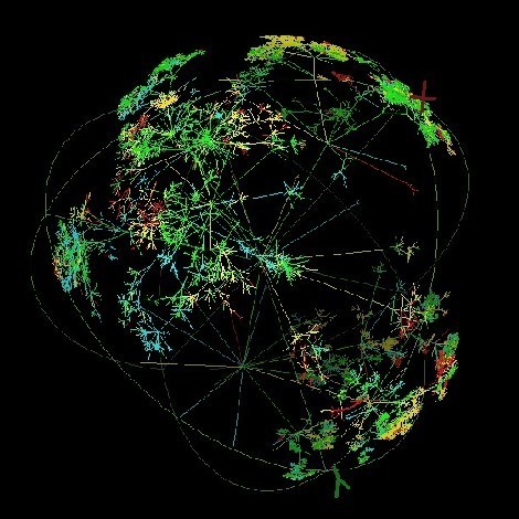
In reality the internet is a huge complex and organic network that spans the globe like a gigantic spiderweb. While it would be interesting to dig into the internet in great depth, we’ll stay with our theme of simplicity.

Map of The Internet

Map of the Entire Internet 2014 – Source : www.caida.org

The Default Gateway

In most small to medium-sized environments there will be a single router that is responsible for taking packets destined for external nodes and routing them accordingly. If the source and destination nodes are inside the same network, then there is no need for a router to be involved as the nodes will usually be connected to the same physical media, have access to the same broadcast domain and can communicate directly.  If the destination node is outside of my network, my source node will automatically send it to my Default Gateway, which is the router that will forward it on towards the external destination.

A Router is essentially just another computer that sits on its own IP address in the network. Rather than having a server or desktop operating system installed, it has a stripped down specialised operating that is optimised for the processes required for routing.  If you look underneath the CLI (command line interface) for the device, you will find that the operating system is most likely a descendant of UNIX or Linux, that has been tailored for this specific purpose.  Traditionally, these devices were built on custom hardware, with custom chipsets designed to perform with rapid speed in mind. This is something that is changing. With the continued exponential performance increases in commodity x86 hardware, the cost/benefit ratio of using custom hardware versus decoupled software backed by commodity x86 servers no longer stacks up in custom hardware’s favour. I’ll address this in more depth in future posts.

The nodes in our network are aware of the default gateway, as they the default gateway address is either configured manually or provided by the DHCP server at network configuration time.  On Windows, the Default Gateway can be identified using the IPCONFIG command:

Default Gateway Highlight

When the default gateway receives our packet, it examines the destination IP address, performs a lookup in it’s routing table to find where to send it and forwards the packet onward to the next router in the journey.  It’s important to note here that the Router might not necessary know the final router’s destination address, it simply knows the address of the next hop or step to take.  The same process happens at each decision point (router) in the journey, until the packet finally reaches it’s end destination. This being the router that is responsible for (has authority over) the network where the destination node is hosted.

How do Routers Know Where to Route?

While it is possible to manually edit the routing table by adding static routes for the next hop of known destinations, routers are thankfully much more intelligent. There are a number of protocols which routers can implement, so that they may automatically discover and share route information. This makes networks very flexible and also able to adapt quickly to change. These protocols are sub-divided into two groups, IGPs (Interior Gateway Protocols) and EGPs (Exterior Gateway Protocols).  IGPs are used in larger environments where an organisation might have multiple routers and many nodes with multiple geographical or logical segmentations. One such protocol is RIP (Routing Information Protocol). EGPs are used at the border between autonomous systems (i.e. at the gateway between networks that are controlled by different entities). BGP (Border Gateway Protocol) is an example of an EGP.

Additional Tags

It is worth mentioning at this point that in addition to simple packet forwarding, modern routers also give us some extra functionality. One area where we can leverage the router is to enforce a certain level of service. We are able to flag each packet with a priority, this comes in the form of a DSCP (Differentiated Service Code Point) tag that we can place in the IP packet header. This can be used by routers that support QoS (Quality of Service) operations to prioritize packets. By default, higher priority packets will be sent first, and lower one’s queued in buffer space until there is bandwidth available to send them. If the buffer capacity fills, the router will simply discard lower priority packets that won’t fit in the buffer. This might sound like a very bad thing, but that’s where TCP would step in for important packets and resend them when the notification is received from the destination that packets haven’t arrived.

The Pirate Ship: In our pirate scenario, we’ll say that the Post Master in the mailroom of my office is my Default Router.  If I wanted to send my Lego package to another room in the building, I wouldn’t bother the Post Master, I’d simply use a different mechanism to get it to the other room which we’ll discuss in future posts. In this instance, I do want to send the package to an external address so the first point it will reach is the Post Master. Before sending the package to him, I have put some additional information on it, in the form of a marking that says “1st Class”. This would be analogous in the IP world of applying QoS tags to ensure the packet receives the appropriate level of service.

He reads the marking and ensure’s the package is dealt with before other lower priority packages. He knows that it needs to be posted at the local Post Office and sends his mailroom assistant on his bicycle to do this immediately. The local post office receives the package, examines the destination address and performs another routing action. As it’s going from Manchester to London, the next hop for the package is to send it to the North West UK Distribution Centre (NWUKDC). It’s placed in a van and sent the same day. Packages aren’t delivered directly from NWUKDC to locations in the South East. They are bulk transported via truck to the South East equivalent Distribution Centre, SEUKDC. From there my package is routed and sent by van to the local London Post office and then by Post Man to Rich’s office door. At each point in the journey the package is examined and sent to the next hop.

Rich’s room will now receive the package from his Postmaster, and he’ll unwrap it accordingly. This will happen for each piece of the ship and as it arrives, it will be reassembled into the full original form.

Next: Networking Primer – Part 6.1: Data Link Layer, Ethernet and MAC

Networking Primer – Part 5.2: Network Layer – DNS and DHCP

Previous:Networking Primer – Part 5.1: Network Layer – IP Addressing

We have seen in the previous section that each node in a network requires an IP address and that four part address is considerably more human readable than the underlying binary bits that it represents. Unfortunately, our meagre human brain power still has trouble with recognising and differentiating between the addresses. For the same reason, we don’t have postal addresses like this: building 1, street 52, town 34843, city 2828, region 292, country 6, we need another method of identifying the addresses of our nodes. This is done with what’s called a Fully Qualified Domain Name (FQDN). A typical FQDN looks just like the one at the top of  you browser: www.bltbytes.com. These names are very easy for us to understand, but the underlying network components can’t understand them. We need a system or method for translating IP addresses to FQDNs and vice versa. That’s where Domain Name System (DNS) joins the party.

Domain Name System (DNS)

DNS is a simple concept. It does exactly what we highlighted above. It provides a way for us to map an FQDN to an IP Address.  The use of DNS in its simplest form involves a client (requestor) and DNS server.  Let’s say that we want to use our web browser to read an article on BLTbytes. When we enter the FQDN (www.bltbytes.com) into our browser address bar and click go, the browser becomes the client in the DNS operation. It will send a query to your local DNS server to ask what the IP Address is for that FQDN. The DNS server will look this up in its database and send it back to the browser. The DNS server then steps out of the loop and the browser will initiate a direct connection to the web server that is hosted at the IP address we have been given.  Simple right?

There is however, a much more involved multi-DNS server architecture that exists behind this process. It would be great if our DNS server could hold every FQDN and IP address in the world in its database and instantly refresh, along with everyone else’s DNS servers every time there is a change, but that would be one very huge database and there would be a massive amount of synchronisation data being transmitted across the internet at any one time. It would ultimately be ridiculously inefficient and not a sensible approach. There would also be a number of difficulties around who own’s what FQDNs and who doesn’t. I’m sure that Coca Cola wouldn’t be very happy if Pepsi decided that their website should sit at www.coca-cola.com.

DNS Tree

The naming scheme on the internet actually breaks down addresses into components that can be authoritatively controlled by those who own the addresses. Another way to refer to those components is as sub-domains or child-domains. This allows us not only to establish ownership of domain names, but also to distribute the management of those components, The data is stored and updated in a distributed manner. Behind the scenes, the naming scheme looks a little like a tree. At the top of the tree we have a root and then immediately below we have domains such as .com, .org, .net, .uk. There are actually only 13 Root DNS servers in the entire world that manage the data for where to find those top-level domains. Below those we see our organisational (or in some cases, personal) names such as “coca-cola”. Then we usually see our individual node addresses, e.g. “www” or “email”. These components make up our full address, www.coca-cola.com. When we send a DNS request to our local server, if it doesn’t own (also referred to as authoritative control) the domain name space, it will contact a root server and then be referred through an iterative process down through the branches of the tree to the DNS server that ultimately owns that name space.

Dynamic Host Configuration Protocol (DHCP)

In the early days of IP networking, all nodes on a network would be manually configured with an IP address. Addressing was not dynamic and therefore we would assign a “static” IP address to each node. Times have certainly moved on. With the explosion of devices and the requirement for mobility and flexibility (e.g. to easily attach to and detach from networks) we needed another way to assign IP addresses. This is where DHCP comes in. Using a DHCP server on our network allows us to create policies for automatically assigning and revoking IP addresses in the network. We can put controls around the types and identities of devices who have permissions to receive addresses. We can also issue a lease on each IP address so we may reclaim them after a defined period of time.

Once a device has physical (whether wired or wireless) access to the network it’s able to start the process of broadcasting requests for an address. This is a simple 4 step process that runs as follows:

DHCP Assignment Process

Once acknowledgement is received the requesting node then starts to use the assigned address in its network stack. It’s worth noting here that the DHCP isn’t giving the node anything tangible. It’s really just saying, you can use that address. It’s possible to configure the node with an address statically regardless of what the DHCP server has done and this is where IP address conflicts may occur. An IP Address conflict is where two or more nodes on the network are advertising the same address. This sort of issue needs to be resolved quickly as it can cause havoc with communications.

While sitting on a network, a DHCP server is ultimately assuming responsibility for handing out addresses and controlling the available address pool, but DHCP does a little more than just hand out IP addresses. It also configures other information on the node, like where it can find DNS and what address it should use to get to outside networks.  DHCP can be used as an attack vector, that hackers could use to gain access to a network. If the attacker gains physical access to the network, they could install their own DHCP server and that server would automatically respond to requests, thus giving the attacker the ability to control some of the network communications.  DHCP will not only provide an IP address it also tells the requesting client where the DNS server is on the network. Can you imagine the control an attacker could have if they have control of DNS? Let’s say you wanted to upload the blueprints for your super secret new game changing widget and the DNS server is telling you that the super secret file server is at one IP address when really, it’s at another. You would have no idea that you are uploading to the wrong place until you realised it wasn’t in the right place.  This has been fixed in modern networking, DHCP servers now need to authenticate with a Domain Controller before they are able to start working on the network.  DNS & DHCP security attacks are a large area to cover and outside of the scope of this primer, but hopefully the example above gives a taste of what is possible.

The Pirate Ship: For simplicity, we’ll keep DNS and DHCP out of our analogy.

Next: Networking Primer – Part 5.3: Network Layer – IP Routing

Networking Primer – Part 5.1: Network Layer – IP Addressing

Previous: Networking Primer – Part 4: Transport Layer, TCP and UDP

The clue might be in the title, but the Network Layer is one of the more important layers in the network stack.  So far we have defined high-level identities, application services and data formats. We have also established our protocols, chopped up data into smaller more manageable pieces and tagged them with a sequence number. It is at this point we need to start defining more details on where we will be sending the data and moving closer to establishing a unique address for both source and destination. We also need network components to be in place to allow us to transmit and route the data appropriately.

Image of 3D IP Address

The two core concepts at work in this layer are addressing and routing.

Addressing: Internet Protocol (IP)

The most ubiquitous protocol used for network addressing and routing is the Internet Protocol, IP (i.e. the IP from TCP/IP). As with most protocols, there have historically been alternatives such as IPX/SPX Novell Netware’s protocol, but these have mostly disappeared as IP has become the defacto standard for data communication. Again, the clue might be in the name here, but it is this protocol that underpins the internet and fundamentally enables everything we do on the internet.

The first thing we need to consider in IP, is addressing. For each node in a network (note: nodes are sometimes referred to as Hosts), we need to provide a unique IP address.  As of today, the bulk of internet communications use IP version 4 (IPv4). IPv4 defines an address as four numbers between 0 and 255, separated by periods  (For example: 135.168.0.23). The format is a little strange and this is due to the underlying need for the systems to convert the more human readable IP address to/from the more computer usable binary representation of the address.

This works very much like a postal address. In a postal address we have a house number, a street name, a city, a region, a country and a post code (USA: Zip Code).  An IP address is much simpler. That four part address is actually  made up of a Host ID (i.e. Node ID) and a Network ID. So really all we need in IP is a house number and a Post Code.  We can split the above address into two parts as follows:

Network ID: 135.168.0
Host ID: 23

For the purposes of this primer, we will keep it simple. In reality, due to the nature of the mapping between binary bits and IP address components. Splitting the address into a Host and Network ID can become much more complex and may straddle the two numbers on each side of a period. You can, for instance, have a node that sits on 135.168.10.2 and another node that sits on 135.168.10.244. One might assume that these are both on the same network (135.168.10) but they could be on different networks. For each node, we apply what’s known as a subnet mask and it is this mask that dictates which Host IDs sit in which networks. There are some moderately involved calculations that happen in the background to decide where the Host to Network split occurs in an address. If you want to do this, my best advice here is to go find a subnet mask calculator.

Networks are also defined by their size, Class A (large: up to 16,777,216 addresses), Class B (medium: up to 65,536 addresses) and Class C (small: up to 256 addresses). There is also a Class D & E but these are not related to size.

A typical subnet mask for a Class C network, looks something like this:

Subnet: 255.255.255.0

IP Network Scope: Private vs Public and NATing

It is worth understanding a little bit about scope here. A network’s scope may be restricted in an isolated room with no connectivity to the outside world. In which case, all the nodes in that room must have unique network addresses. Let’s call it Room 1. If we have another similar room (Room 2) of nodes all isolated from the outside world, those nodes could have the same addresses as those in Room 1. There is no requirement for uniqueness as the isolation of the two networks means there is never any confusion over which node has which address as they never communicate between rooms. This is most commonly referred to as a private network.

On the internet, all addresses must be unique but due to the exponential growth of the internet, public IPv4 addresses have become scarce as there simply aren’t enough of them to hand out. This has led to organisations implementing architectures where they can minimise the use of public IP addresses. An organisation might only have one public IP address, but many hundred’s of nodes inside their network. So how do all those nodes talk to the outside world? This is done through a process called NATing (NAT – Network Address Translation).  The analogy with the postal service here, is that an office building may have a front door number (Public IP Address), but lots of room numbers inside (Private IP Addresses). Different buildings will have different front door numbers, but inside their is nothing stopping them having the same room numbers (Room 1, Room 2, etc).

The NATing process is responsible for handling the conversion of private IP addresses to public ones and back again. You can think of this as a mail manager sitting at the front door. When someone from Room 1 sends something out of the building, the mail manager logs it’s destination in a table and the fact it came from Room 1. In the destination building, the receiver doesnt necessarily know it’s from Room 1, they just know that it came from that building. If they respond, the mail manager checks his table sees that the originating communication came from Room 1 and sends the reply back up to Room 1.

Public and Private IP Example

In fact, even today it is very likely that your own home uses this concept of public and private IP addressing. If you have broadband at home, the router that your ISP provided will manage a pool of internal private IP addresses that are handed out to your devices (Computers, IPads, TVs, etc) and a single public IP address that the provider uses to identify you on the internet.

Note: There is a new IP protocol which has been available for some year, IPv6. This resolves the “running out of addresses” problem, but isn’t widely deployed today.

Let’s take a look at the IP configuration on your system. Note: PC/Laptop only:

  • Go to your Start Menu and search for and run “Windows Powershell”. This may be in a slightly different location depending on your version of windows. At the Powershell prompt: Type “IPCONFIG” and see the results. You should see something like this:

    IPCONFIG Powershell Screenshot

    Some of the items listed will be recognisable, such as IPv4 address and Subnet Mask. There are also some other items like Default Gateway which we’ll cover in later posts.

  • Open up a terminal window and type IFCONFIG. On a Mac you will see a result that looks like this:

    IFCONFIG Screenshot

    I’ve highlighted some of the same information that you could also see on the Windows tab. The output here is a little more complex and has much more content. We can see our IPv4 address “inet 192.168.0.2” and also our subnet mask “netmask 0xffffff00”. You’ll notice that the subnet mask is much less recognisable and this is because it’s displayed in hexadecimal format, instead of standard IP or binary. If you convert the hexidecimal to IP, you get 255.255.255.0 which is a standard Class C network subnet mask.

    Linux produces a similar format to this with some slightly different details, but ultimately following the same approach. As you might expect Linux and Mac systems have many similarities due to their sibling nature and UNIX ancestry.

IP addresses are clearly an important factor in the network layer, but even though we have a unique network identity for both our source and destination nodes, they wouldn’t be of much use if we didn’t have a way to direct the data packets across the network from source to destination. That’s where routing comes in.

The Pirate Ship: Let’s use some of the similarities with the postal service in our analogy. Instead of an IP address we’ll have:

My node address as:  Room 62, Building 34, Legofiend Street, Manchester.
Rich’s node address as: Room 78, Building 2, Zoo Street, London.

We’re going to assume that all addresses are public and that there’s is no NATing process occuring between public and private. To align more closely with IP Addressing, let’s split our addresses into a Node and Network ID. So, in both cases the “Room” is the node and the “Building, Street, City” part of the address makes up the network ID.

To pick up where we left our transport manager earlier in the series, we need to apply more information to our packet. It currently has a TCP label and sequence number.  We’re now going to take that packet and put it inside another one, a slightly larger box. On the new package, we’re going to write the destination node address (Rich’s) and the source node address (Mine).

Next: Networking Primer – Part 5.2: Network Layer – DNS and DHCP

Networking Primer – Part 4: Transport Layer, TCP and UDP

Previous: Networking Primer – Part 3: Application, Presentation and Session Layers

The transport layer is responsible for providing reliable data transfer services to the upper layers of the OSI stack. It is at this stage that we start to consider actually sending the data. This layer also involves the segmentation/desegmentation of data into smaller chunks. It is very rare that a network will be configured to take a large payload from one source node to a destination node. This is why we will segment the overall data payload into smaller pieces. This is also the first place in the stack where we start to apply some addressing so the destination node understands which listening receiver the data is intended to reach. This address comes in the form of a port number. The destination node may be simultaneously listening for (or have the ability to connect to) different network services and the way we distinguish between these services is by giving them a different port number. For example, web server usually listen on port 80 where email servers will listen on port 25.

Connection-Orientated vs Connection-less Protocols

There are essentially two flavours of protocols that exist in this layer.  Connection-orientated protocols will involve communications that must be received without data loss with the data arriving in a certain sequence. Transmission of legal or financial documents would fit into this category. The applications at both sending and receiving end have an expectation that the documents will be received in full and with the correct format. An example of a connection orientated protocol is the TCP (Transmission Control Protocol) protocol which makes up the TCP out of the TCP/IP suite.  The TCP sender will break down data into TCP segments.  It will send each of these across what may possibly be an unreliable network. Due to the nature of packet switching networks, although each of these packets may have been sent in sequence it is possible that they may get routed differently and arrive out of sequence.  At the receiving end, the TCP receiver will take the data re-sequence it if the packets have been received in the wrong order and also send a request back to the source, if any of the packets are missing.

Connection-less protocols, such as the UDP (User Datagram Protocol) don’t have the same level of error-checking and control. In a connection-less transmission, packets are sent in sequence but they are sent with the best effort approach.  There is no checking to see if the packets were received and no resequencing of packets at the destination node.  So why use connection-less? Well, not all applications need data transmissions to be without loss. For example, if you are streaming online video and the packets for that live video are received slightly out of sequence, or the occasional packet is dropped; this doesn’t make much difference to the overall viewing experience at the destination node. A huge benefit of this approach is that the protocol is much less chatty, therefore can provide better performance with less bandwidth.

The Pirate Ship: To continue our analogy, let’s imagine that I have a transport manager in my office and Rich has a transport manager in his office. In this case my transport manager is going to use the connection-orientated TCP protocol. This is because he needs to break down the Lego bricks into segments (individual blocks) and send them reliably across to the destination.  All the blocks must be received at the other end and they must be reassembled in the right sequence in order to reconstruct the ship. To do this he takes each individual block and puts it in a small parcel, he then writes on the parcel the protocol (TCP), a port number and sequence number.  This is where the transport manager’s responsibility ends, he will  listen to find out if any segments were not received and then resend these, but for the actual movement of the parcels other entities further down the stack will take over.

Next: Networking Primer – Part 5.1: Network Layer – IP Addressing