
Previous: Networking Primer – Part 6.1: Data Link Layer, Ethernet and MAC
I will start this post with a foreword that at least one of the protocols in the title, CSMA/CD, is obsolete. I’m including it here as it’s very useful to understand why we no longer need it, due to the changes in layer 2 topologies that have evolved over time. A little history can illuminate why we are where we are.
CSMA (Carrier Sense Multiple Access) is a methodology that deals with multiple computing nodes access the same physical media, whether that be a piece of wire, optical fibre or even the air. It makes sense that there should be some rules around when each node can transmit/receive rather than a free-for-all where interference, possible corruption and inefficiency can occur. The media is being shared so access needs to be given through arbitration.
There are two sub-methodologies for CSMA. These being CSMA/CD (Collision Detection) and CSMA/CA (Collision Avoidance).
CSMA/CD history
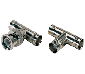
As mentioned in the previous post, initially Ethernet systems were based on coax (coaxial cable). Networks were implemented in a bus sharing topology. All of the nodes in the network would share the same piece of coax and essentially have their NIC connected to a piece of coax that was piped directly into the main bus coax via a T-Bar connector, that looked like this:
You can see a typical network bus topology here:

In order to ensure communication between the nodes could occur. CSMA/CD was used. In CSMA/CD, each node would step through a process to get the desired result. The process was as simple as:
- Listen to see if the wire is idle.
- If idle, transmit the data.
- If a collision occurred with another node transmission, wait a random period of time then try again.
In this topology, we have to be aware that the wire represents what we call a “collision domain”. While using a single collision domain (i.e. wire) was reasonably efficient for a small number of computers, it had many problems with reliability and scale. From a reliability perspective, if there was a break anywhere in the wire, it would take down the whole domain. Another common problem was the absence of or faulty terminators (labelled Terminating resistor above). Without a functioning terminator on the end of the coax, the bus wouldn’t function. A secondary issue here was scale. The more nodes you added, the more collisions you’d see and the less well the network would function.
There were several approached developed to mitigate these issues, revolving around the idea of breaking networks down into smaller segments and therefore smaller collision domains.
Network Hubs
The coax bus topology was soon dumped in favour of using Twisted Pair (TP) cabling and a star/mesh based topology. In order to move away from the single wire bus topology, a new device needed to be introduced to act as the central connection point for the network, as each node would now have it’s own wire. Enter the hub. A hub is essentially a box with a bunch of ports on it. Each node can be plugged into a separate port on the using it’s own TP cable that has an RJ45 connector on each end. Using a star topology, with our nodes sitting on spokes around our hub, does resolve some of our reliability problems. If a wire breaks or is faulty, only the node sitting at the end of it is affected and not the whole network.

The hub is, however, a very dumb piece of equipment. It takes frames in on any single port and then sends those frames out to every other port. From a collision perspective we still only have a single collision domain. This means that we still have to use CSMA/CD and we still have problems with scaling.
Network Bridges
A network bridge is an additional network device that has a little more intelligence, but only a small step up from a hub. A bridge only has two ports, it sits between two network segments and learns which mac addresses sit on either side of it. If it sees a destination MAC address coming in from side A, and it knows that the destination node is on side A, it will drop the frame. Therefore, none of the nodes on side B will ever see it. We have reduced our network traffic by 50% on each side and also halved our collision domain.
Network Switches
While Hubs and Bridges made significant strides in improving both reliability and reducing collision domains, it was clear that scale and management were still difficult for any network that was larger than a few 10’s of nodes. The network needed additional intelligence. That intelligence came in the form of “Switching” and the new device to do that was the “Network Switch”.
The switch takes things much, much further. A switch has more than two ports, topologically it can be used instead of a hub. In the same way as they do to a hub, each of the nodes connects directly into the switch on a port. The switch is able to do the same sort of filtering that a bridge does, but it can do that on a per port basis. Rather than separating two network segments like a bridge, the switch is separating each and every node. When a frame comes in on one port, the switch is intelligent enough to send it out only on the port (or ports) where it needs to go to, to reach its destination. It has the intelligence to learn which MAC Addresses are sitting on which ports and updates its own internal tables as this changes.
Circling back to our title, bus using a switch we have effectively reduce our collision domain to a single wire per node. We therefore no longer need a methodology to arbitrate access to the media. Hence the obsolescence of CMSA/CD.
This is as deep as we’ll go on switching until the next post.
CMSA/CA – Carrier Sense Multiple Access – Collision Avoidance
CSMA/CD is very much the bull in a china shop, feet first approach to accessing physical media. CSMA/CA represents a more cautious approach with the goal of avoiding any collisions in the first place. It is still relevant and prevalent today due to the nature of WiFi networks.
In a WiFi network, the physical media is essentially the air (or radio waves running through it). As you can imagine, it would be very difficult to segment air in the same way as a wired network as there are no clear points in ingress/egress. We could try to use the CSMA/CD approach, but this isn’t effective in WiFi as each node communicates directly with the wireless AP (Access Point) and not with each other. This is called the hidden node problem, where collisions can’t be detected so the node never knows one has occurred. By using CSMA/CA, the WiFi network is able to work around the issue. With this methodology the AP mediates access to the media. A node requests permission to send, the AP gives the node a CTS (Clear To Send) acknowledgement and the node will send its entire payload across the channel. Only one node at a time has access to the channel.
Now we have successfully accessed or media and pushed our frame out of the source node, let’s look at how that’s moved across the LAN.
Next: Networking Primer – Part 6.3: Layer 2 Switching – Loops, Spanning Tree and Topologies